AR-45
Lower Receiver
Project |
History
This
website contains intellectual property
belonging to CNC Gunsmithing / jwh02017
The
AR45 design is currently patent pending
It's
time for something a little bit
different. The same guy who shared
with me his idea of the A1 detachable
carry handle, William Putnam, also
dreamed up another idea. He wanted
to use M3A1 "grease gun"
magazines (which are .45 caliber) in an
AR15 with a .45 cal. upper
receiver. Olympic Arms sells .45
cal. upper receivers but they come with
a modified Uzi mag with a built-in mag
well block. The mag is single
stack, so it's not real high capacity
mag. William was wanting to use
the grease gun mag so you could have
more trigger time between reloads.
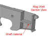
The problem with using grease gun mags
is that the body of the mag is about the
same width as the outside of a normal
AR15 mag well. So you can't simply
modify the AR15 receiver and expect it
to work. In order to get this to
work, a brand new receiver would have to
be machined from a billet of material to
allow for a wider mag well. One
company has attempted this idea, but
they used plastic receivers which aren't
very versatile, as you can't change out
the stock and pistol grip to fit your
needs. They also used a mag catch
similar to that of the AK-47. With
that method, you have to hold the rifle
with one hand, and then with the other
hand grab and release the mag, then
reach for another mag and insert it in
the receiver. I wanted to stick
with a normal AR15 look and feel.
I wanted to be able to drop the mag by
pushing the mag release button with same
hand I am holding the rifle with while
at the same time reaching for another
mag. This method would be alot
faster than the AK47 style of mag
release. I also didn't want to
move the location of the mag release
button, since AR15 users are already familiar
with it's current location. So I
started to work on the solidmodel design
of the receiver and I came up with
something I thought would work.
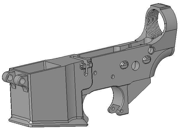
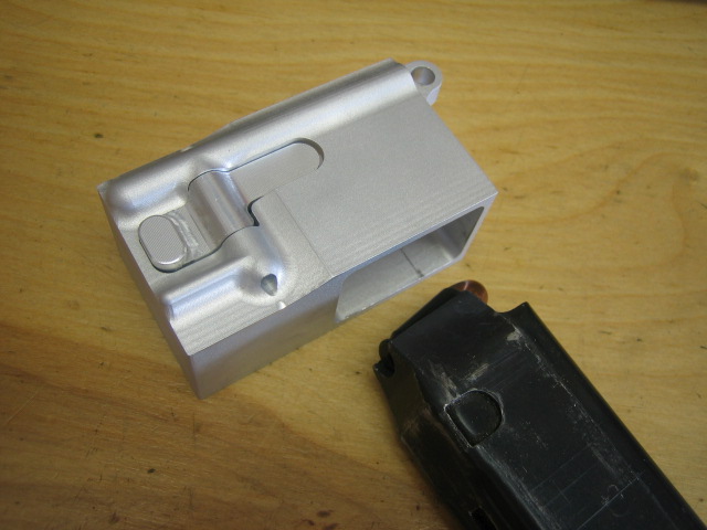
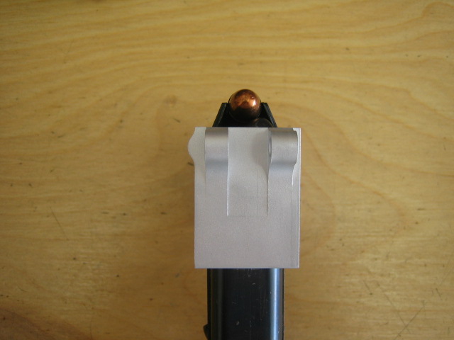
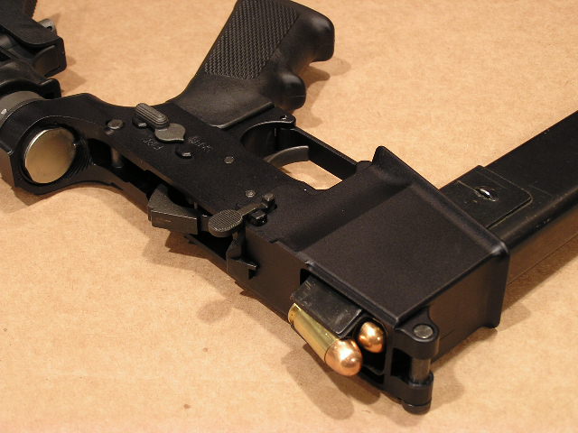
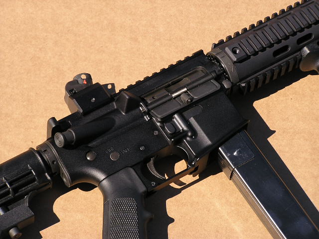
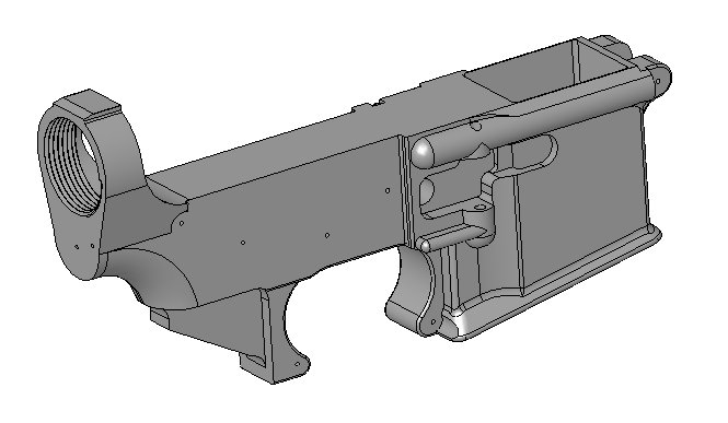
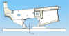
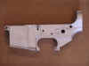
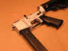
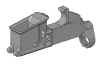
I'm going to call this new design the
AR45. It will be using an Olympic
Arms .45 cal upper receiver. In
the pic above you can see how the mag
well is wider than that of an AR15
receiver. I'm not going to give a
whole lot of details about how it's
going to work just yet, but I'm 99% sure
it will work. I have already made
a test piece and it worked
perfectly. As I get closer to
finishing the receiver, you'll see
exactly how this design is going to
work.
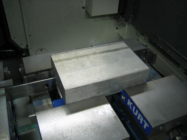
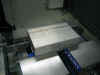
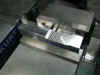
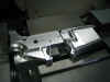
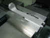
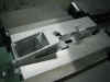
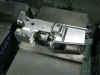
I
started machining the 1st operation
of the AR45 receiver. I'm starting
out with the same size block as I did
with the AR15 lower receiver: 5" x
2" x 7.9" Below you can
see what the billet of material looked
like in the machine...
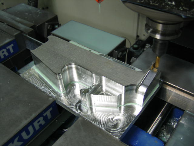
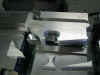
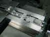
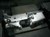
I
first roughed the outside profile of the
receiver with a 1/2" hog endmill
and made a clean up pass with a
3/8" carbide endmill. Then I
used a 1/4" ball nose carbide
endmill to machine the profile of the
receiver. In the pic below you can
see how the 1/4" is starting to
profile the receiver...
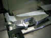
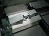
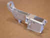
Here
it is a little further along...
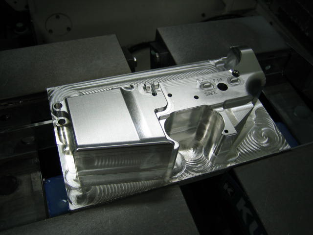
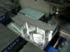
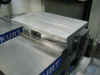
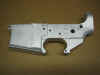
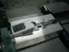
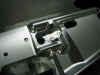
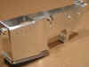
After
some detail milling was done and some
holes were drilled, the 1st operation
was finished. Below you can see
what it currently looks like...
I
probably won't give a step by step of
every tool I use while making the
AR45. That's because this receiver
is very close to the AR15 lower
receiver. But I will show each
operation along the way. Some of
you may have noticed the the spirals on
the bottom of the receiver left over
from the roughing process. Always
before hogging out material consisted of
zig-zag and rectangular movements to
remove the material. The CAM
software we use just came out
with a new way of roughing material. This
new technology manages the tools engagement
with the material, so you never bog the
CNC machine down. So the CAM
software now knows to slow down in the
corners and speed up on straight line
moves. It also knows not to just
plunge right into a square corner.
Instead, it kinda carves the material
away until it reaches the corner of the
pocket. Before, a normal feed rate
for hogging out material would be around
125 IPM, but now you can hit 650 IPM at
a depth of 1/2" without breaking a
tool!!!
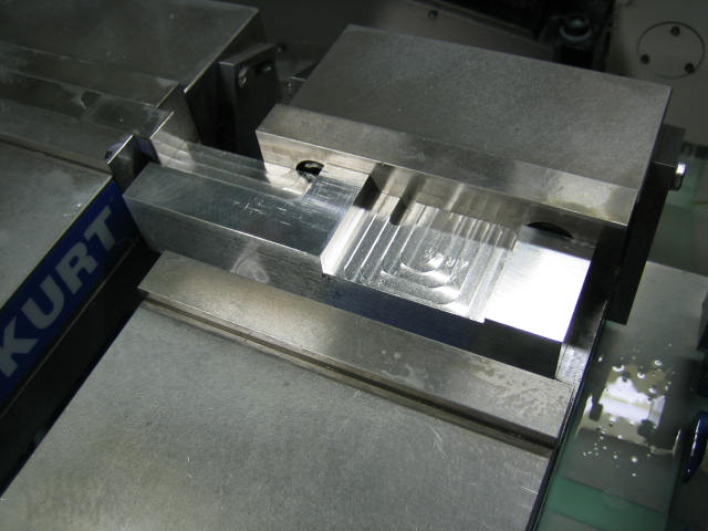
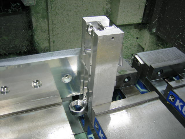
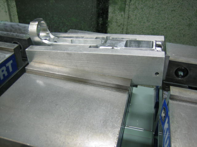
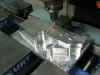
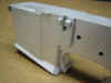
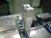
For
the 2nd operation, I'm going to
be removing the slab of material on the
right side of the receiver. In
order to hold the receiver flat and
square, I used a pair of my old style
AR15 setup blocks. Since the mag
well on the AR45 receiver is wider, I
had to modify a couple surfaces on the
blocks. I could have used the new
style setup blocks, but I had a set of
the old style just laying around taking
up space. Here is a pic of what
the block looked like in the vice...
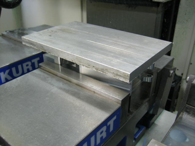
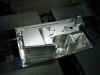
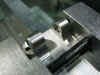
Here
is what the receiver looked like at the
start of this operation...
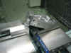
I
used a 1/2" hog endmill to rough
the outside profile of the
receiver. If I didn't remove these
pieces of material, the receiver would
have the tendency to be jerked out of
the vice while it's being flycut to the
correct thickness. Here is what it
looked like after I removed these pieces
of material...
I
then used a 3" shell mill to flycut
the receiver to the correct
thickness. Then I came back with
the 1/2" hog endmill to rough more
of the material out...
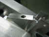
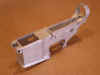
Next
I used a couple more endmills, a drill,
and a 1/4" ball nose carbide
endmill to finish out the 2nd
operation. I haven't made the cut
for the mag catch yet. That will
have to wait until further down the
road. If I tried to cut the mag
catch now, I'll have a conflict on one
of my other operations. Here's
what it looks like...
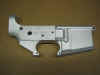
Here's
a few more pics of what the receiver
looked like after it was bead blasted...
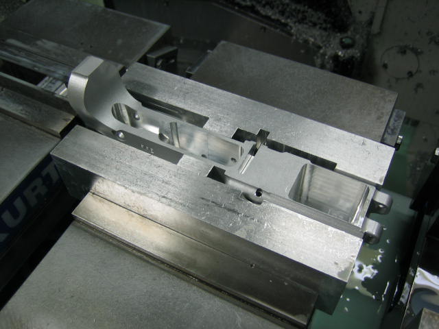
For
the 3rd operation, I'll be
machining the top plane of the
receiver. This includes the fire
control area and the magazine
well. I'll once again use a set of
my AR15 setup blocks to hold the
receiver in the vice. As I
mentioned before, these are a set of my
old style setup blocks, but the current
setup blocks I sell could have done the
exact same thing. In the pic below
you can see how the receiver was setup
in the vice...
After
using a roughing endmill and a few
finishing endmills, I had the 3rd
operation finished. I only
machined half of the mag well on this
operation, I'll finish it out on the 4th
operation. The reason for this is
because it's hard to reach the full
depth with an endmill while at the same
time keeping it from chattering too
much. Here's what the receiver
looked like at the end of the 3rd
operation...
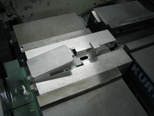
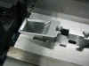
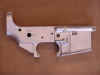
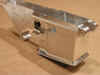
On
the 4th operation, I machined the
bottom of the receiver. This
operation also finished out the bottom
side of the magazine well. Here is
what the start of this operation looked
like...
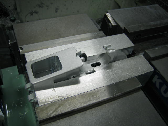
Below
is a pic after the mag well was
machined. You can also see that
the slots for the trigger guard were
also machined...
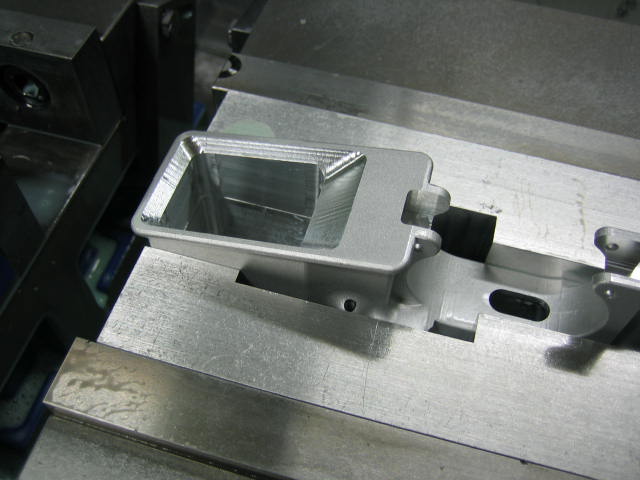
Next,
I used a 1/4 ball nose carbide endmill
to 3-d profile the angle on the mag
well. Here are a couple pics
showing what this tool done...
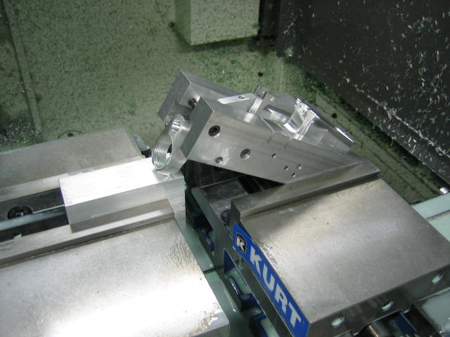
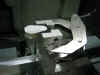
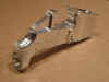
For
the 5th operation, I stood the
frame on end and machined the buffer
tower. Here you can see the setup
I used...
And
here is what the receiver looked like
after the 5th operation was finished...
On
the 6th operation, I drilled the
front take down pin detent hole.
Below you can see what the setup looked
like...
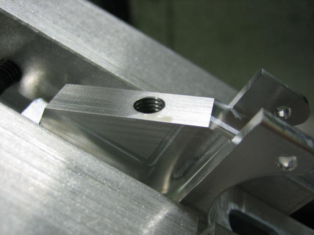
The
7th operation drilled and tapped
the pistol grip hole. I used a
2.5" block to prop the receiver up
on one end. This block made the
pistol grip hole surface parallel with
the machine. Below you can what
this operation done...
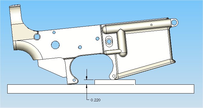
For
the 8th operation, I drilled the
buffer detent hole. This hole is
in at a 6 degree angle, so I had to prop
the end of the receiver up. To do
this, I placed a 0.220" block under
the front trigger guard surface.
Below is a sketch showing how this block
was used...
And
here are a couple pics showing the setup
and what the receiver looked like after
it was drilled...


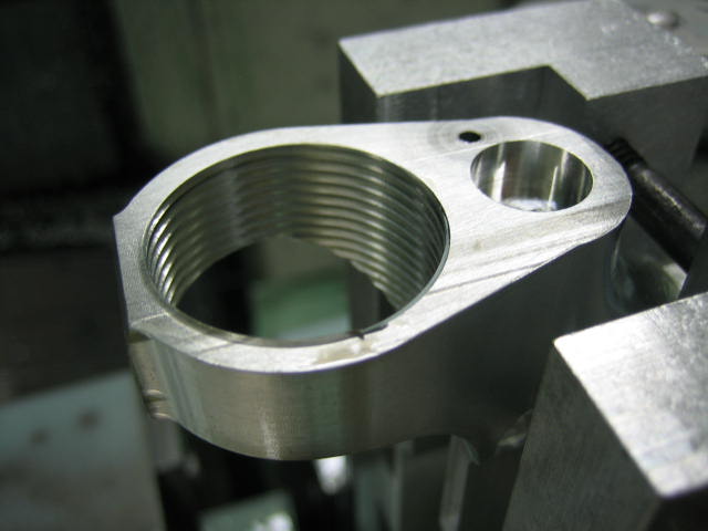
On
the 9th operation, I finished
machining the right side of the
receiver. Here is where I machined
the pocket for the mag
catch. I couldn't have
machined this pocket on the 2nd
operation, because there is a hole
drilled from the top on the 3rd
operation. If this pocket was
machined on the 2nd operation, it could
have caused the drill to walk off
position since the drill would have to
pass through the pocket area before it
finished drilling through the
receiver. Here is what the setup
looked like...
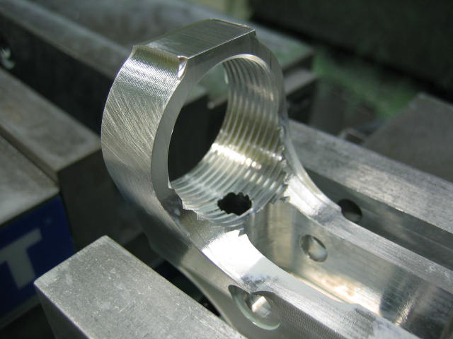
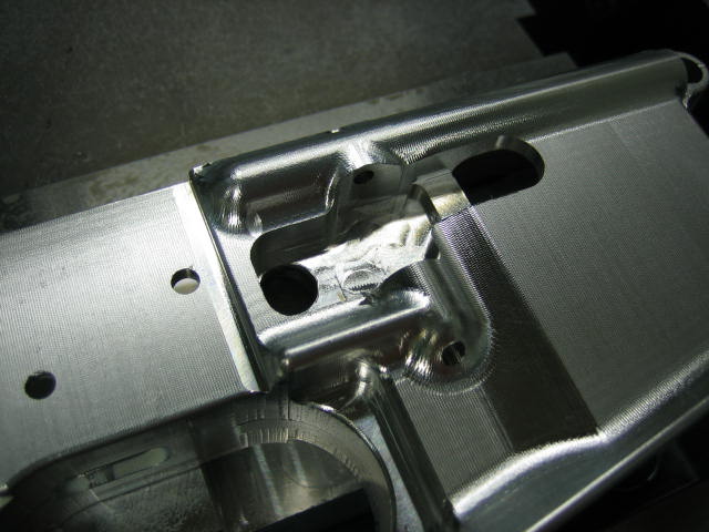
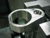
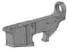
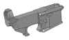
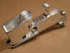
And
here is the receiver after all the CNC
operations were finished.
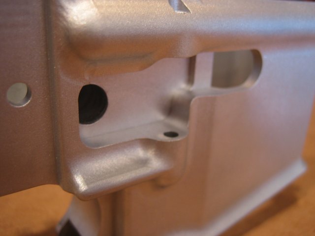
Notice
the 5/16" hole inside the
pocket. This hole houses the mag
catch spring. This is the same
spring from an AR15 mag catch.
When I designed this new AR45 receiver,
I didn't want to make a whole bunch of
new parts. So to keep the design
simple, I used the mag catch spring from
the AR15. This design is so simple
that it only requires one new part to be
made, the mag catch itself. All
grease gun magazines have a
"D" or "square"
shaped pocket on the right side of the
mag. So to catch the mag in the
receiver, I designed the mag catch to
catch inside this pocket on the right
side of the receiver. This will
allow the same mag release layout as the
AR15 receiver. Before I started
the machining on the AR45 receiver, I
made a test part. The test part
would allow me to see how well the new
mag catch design would work. In
this test part I made an aluminum mag
catch. The aluminum mag catch
worked perfect, but it wouldn't hold up
very long riding against a steel
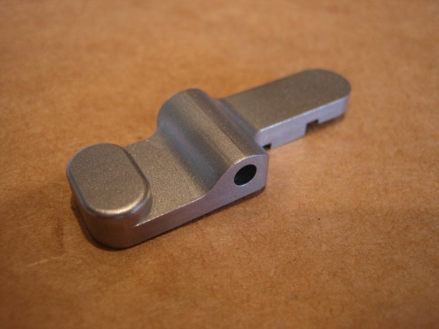
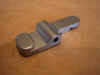
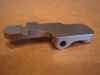
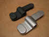
magazine. So I
made the new mag catch from 4140 chrome moly steel.
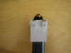
Below you can see what the new steel mag
catch looks like...
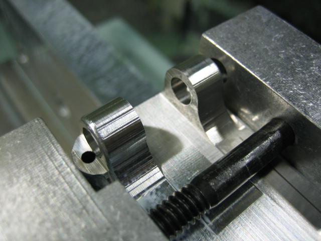
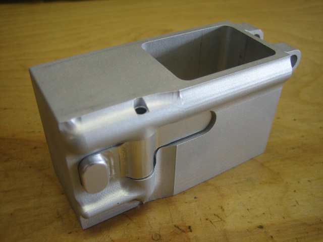
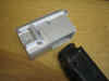
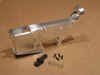
In
the pics below you can see what the test
part looked like.

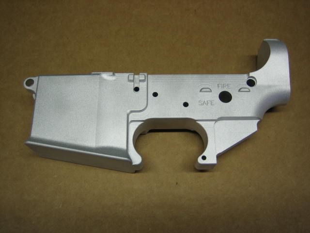
I
tweaked the mag catch design a little
bit, and then I started on the actual
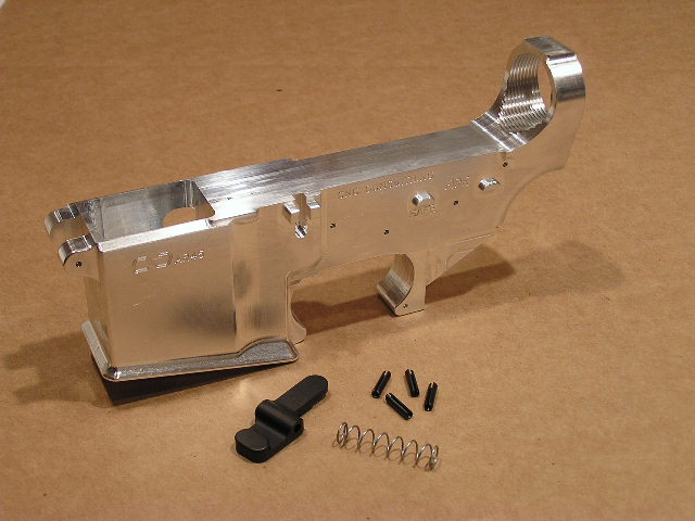
AR45 lower receiver. Since the
machining on the AR45 receiver is now
complete, I gave it a bead blasted
finish and took some new pics before I
started assembling the parts to complete
the rifle. In the pics below, I
haven't drilled the bolt catch hole
yet. I drilled this hole with my
AR15 drilling jig after I took these
pics. (The AR15 drilling jig is for sale
under the Tooling section at the top of
this page).
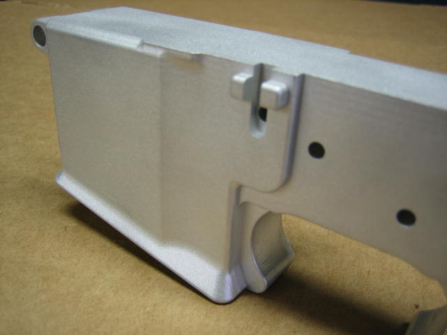
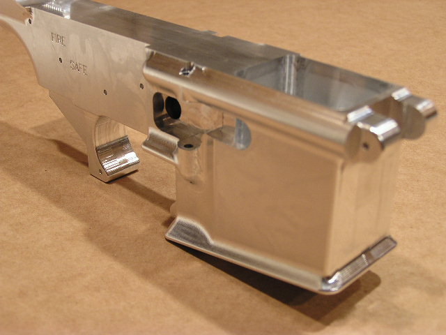
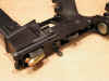
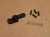
There
are two 1/2" roll pins that secure
the mag catch in the receiver.
There needs to be two roll pins this
length because you could never drive out
one long roll pin because the lip from
the mag well sticks out too far on the
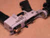
bottom of the receiver. The pic
below shows a close up of the mag catch
pocket in the receiver.

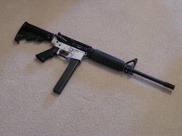
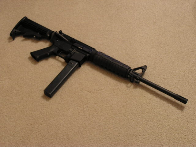
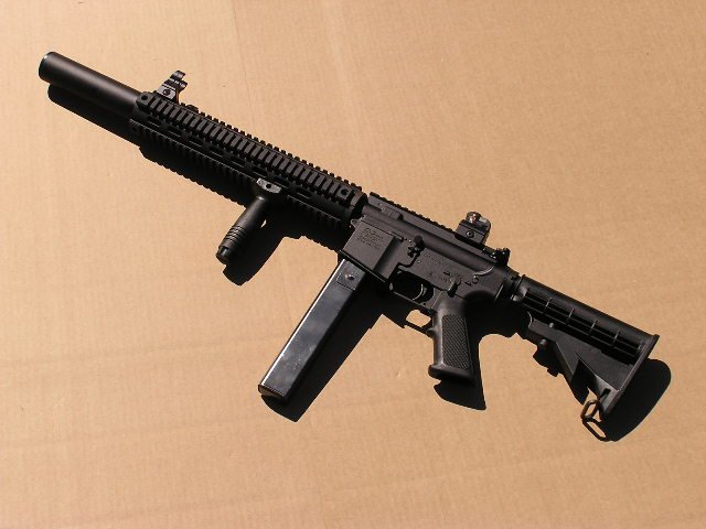
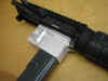
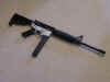
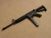
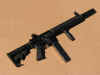
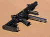
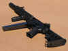
I
assembled all the parts on the lower
receiver and attached my Olympic Arms
.45 caliber upper receiver. Now
the rifle was complete and ready to be
test fired. Below are a couple
pics showing the complete rifle...
I
grabbed a 100 round box of Winchester
white box .45 cal. ammo from Wal-Mart
and couple grease gun mags and I headed
out to the field. I had some .45
dummy rounds that I tested out first to
insure the rifle would load a round properly,
as well as eject it with no
problems. There were no problems
with the dummy rounds, so I popped in a
mag with live ammo. I was kinda
leery at first, because I didn't know
what to expect since I had never shot a
.45 caliber AR15. I shot the first
round, no problems. I shot the 2nd
round, no problems. I ended up
shooting the whole 100 round box of ammo
without one problem what so ever.
Shooting the .45 caliber round in the
AR15 is SWEEEET!!! I enjoyed
shooting it so much that I grabbed the
extra ammo from my concealed carry,
and loaded up another grease gun
mag. I didn't know the AR45 was
going to be this much fun, otherwise I
would have grabbed another couple
hundred rounds. The cool thing is,
the AR45 isn't very loud at all. I
started out shooting with hearing
protection, but half way through I
decided I didn't them it. It is no
where near as loud as a .45
pistol. After the testing of the
AR45, all I can say is AWESOME!!!!
Below
are a couple close up shots of the lower
receiver...
I'm
now going to strip the receiver back
down to bare aluminum and black anodize
it. I'm not 100% sure, but I think
I may parkerize the steel mag
catch. I'll upload some more pics
after the rifle is 100%
complete.
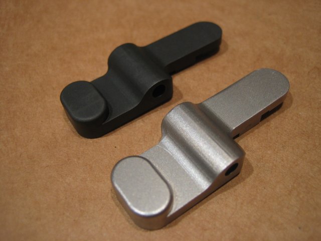
I
decided to parkerize the new mag
catch. I ended up using some palmetto parkerizing
solution that I left over from previous
projects. I used the manganese
type solution. Below is what a raw
mag catch looks like compared to one
that has been parkerized...
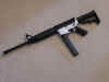
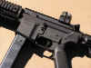
I
then black anodized the AR45 receiver
and reinstalled all the parts.
Below are some final pics of what the
rifle looks like...


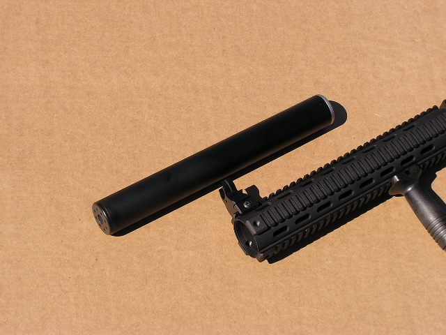
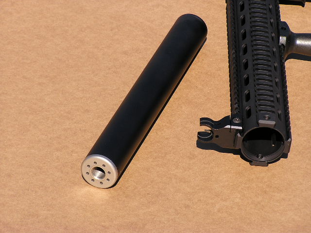
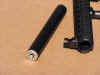
I
finally got my short barrel rifle (SBR)
and silencer paperwork back from the
BATF for my AR45. The whole
silencer is made of 6061-T6
aluminum except for the stainless steel
end cap that is threaded onto the
barrel. The aluminum parts are
black anodized and the stainless end cap
is just bead blasted. Below are a
couple pics of the silencer...

Here
are a couple close up pics of the
receiver...

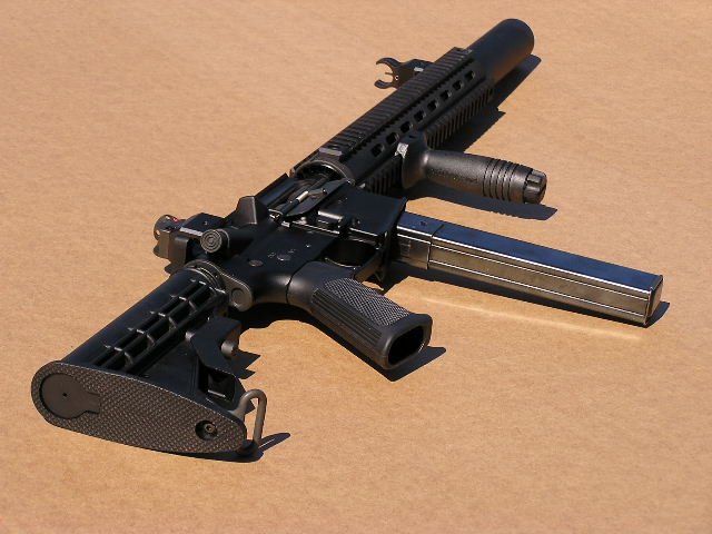
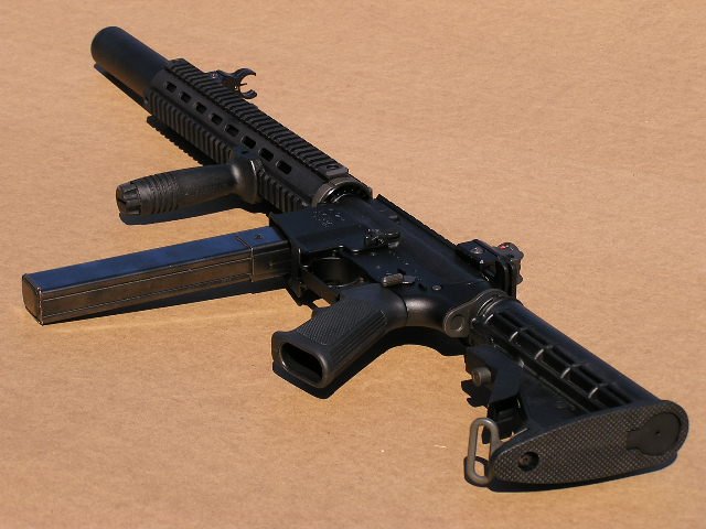
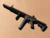
And
here are some final pics of the SBR AR45
with the silencer...
I
used a simple cone design for the
silencer design. The first time I
shot the rifle, I was kinda disappointed,
because I thought it was a little louder
than what I was shooting for. I've
never shot a .45 silencer, so I really
had nothing to compare it to. I
guess I was looking for "movie
quite". I then removed the
silencer and shot the rifle, and WOW,
man does the silencer make a
difference. After I shot the rifle
without the silencer I became very happy
with the silencer. I would guess
this rifle with the silencer sounds a
little quieter than a .22LR. It's
kinda a different sound though, it's not
that really high pitch sound like the
.22LR has. It's more of a low
pitch sound. This setup is not
"movie quite", but it's quite
enough for me.
Below is a pic of Thomas R. Walsh of Falken Industries working a diplomatic protection detail in northern Virginia carrying an 8” barreled SBR AR45 he built using an original batch 1 CNCGUNS AR-45 lower receiver.

--DISCONTINUED--
10%
AR45 lower receivers -
"paper weights"
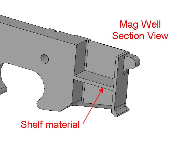
The 10% receivers will basically be the outside profile of the AR45 receiver, with most of the holes center drilled ("center drilled" means the holes will be pre-marked but not drilled) into the side of the receiver (from the 1st and 2nd operations).....and maybe have the buffer hole drilled and tapped. I'll machine half-way down inside the mag well on the top and bottom operations. This will leave a thin shelf of material (around 0.125" thick) that'll have to be knocked out (see pics below). And I'll of course have my AR45 mag catch design milled into the receiver, with the steel mag catch included. For instruction on how to complete the lower, you'll need nothing more than an AR15 lower blueprint. Everything dealing with the AR45 features will be done. Here are a few pics of what the 10%'ers will basically look like...
100% and 80% AR45 lower receivers
**********
Please visit this
link for the latest updates on the
AR45 lowers **********
**********
Please visit this
link for the latest updates on the
AR45 lowers **********
**********
Please visit this
link for the latest updates on the
AR45 lowers **********
Click
here for the AR45 PURCHASE
ORDER form.
Be
sure to email me when sending
payment justin@cncguns.com
To get
more details and to discuss
the AR45 with others, then please visit
the AR45 section in the forum.
NOTE:
The AR45 uses unmodified grease gun
magazines and a standard AR15 lower
parts kit. Grease gun magazines
are manufactured with pretty sloppy
tolerances so you may find some mags
that fit the AR45 mag well just fine and
then you might find some that are a
little snug or won't fit at all.
If this is the case then it's an easy
fix.... just determine if it's the width
or the length that needs to be tweaked
and then just simply squeeze the
magazine very lightly in a vice.
I've purchased magazines from several
different sources and I've never ran
across a grease gun magazine that
wouldn't work in the AR45.
**********
Please visit this
link for the latest updates on the
AR45 lowers **********
**********
Please visit this
link for the latest updates on the
AR45 lowers **********
**********
Please visit this
link for the latest updates on the
AR45 lowers **********
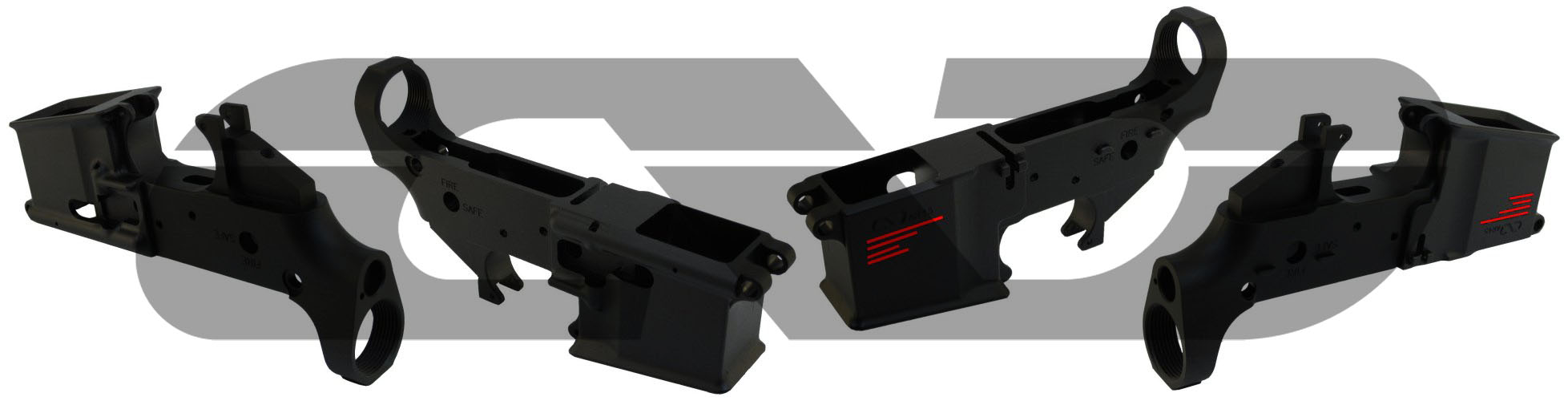
Below you will see what the finished
product looks like. The red lines
in the photo is just there to hide the
receiver info for this pic.
I've
uploaded a couple videos to youtube
showing the AR45 in action. The
first video shows how the AR45 functions
with a slidefire buttstock. The
2nd video demonstrates how a silencer
can work on the AR45. Click on the
images below to watch the videos....


AR45
Upper Receiver Assemblies
I've
had really good luck with the Olympic
Arms .45 ACP upper receiver
assembly. Here's a link.
Since you will be using grease gun
magazines with the AR-45, then you can
save a little money by telling them you
don't need their special .45 plastic
magazine.
The
Oly Arms upper receiver assembly is a
blow back system. If you prefer a
DI upper assembly then I would recommend
buying a custom upper assembly from Rudy
at Quality Machine rudyk@maconarmory.com
This
website contains intellectual property
belonging to CNC Gunsmithing / jwh02017
The
AR45 design is currently patent pending