AR-15 Detachable Handle

After I finished the A3 upper receivers, I decided to buy a detachable carry handle so I could at least have a rear sight on the flat top upper. I bought one of the standard detachable carry handles (de-handle) that everybody sells, but after I received it, I was very unhappy. The first time I put my fingers through the handle, my fingers almost got stuck in the gap. If I would have known the handle would have been this low cut, I wouldn't have bought it. I didn't install the de-handle, and it still isn't installed today. I started looking at the handle to see how much work it would take to machine, and I decided if I could machine an upper receiver, the de-handle shouldn't be a problem. So I started taking dimensions to make the solid model (the CAD part). After I started the work on the solid model, I realized why companies make this de-handle finger gap so small. They do it because they have to have the rear sight a certain height from the top of the receiver. But I didn't let that stop me. I started thinking of a way to work around this. I ended up raising the finger groove gap to 1" tall compared to the standard 0.725" gap that most companies use. I done alot of design work to get just enough gap in the handle so my fingers could slide in, but still keep the rear sight the same height from the top of the receiver. If the finger gap is raised too much, you wouldn't be able to locate a target using the peep sight since the handle height would be too tall. After I had the new handle machined and the rear sight installed, I saw that I made the design just about perfect. With the rear sight at the lowest position, I could clearly see the front sight, the only thing is that I could barely see the inside groove of the de-handle when I looked through the peep sight. But this didn't affect anything since I could still locate a target with the peep sights, and if you raised the rear sight adjustment you couldn't see the de-handle groove at all, so I was very happy with my new de-handle.
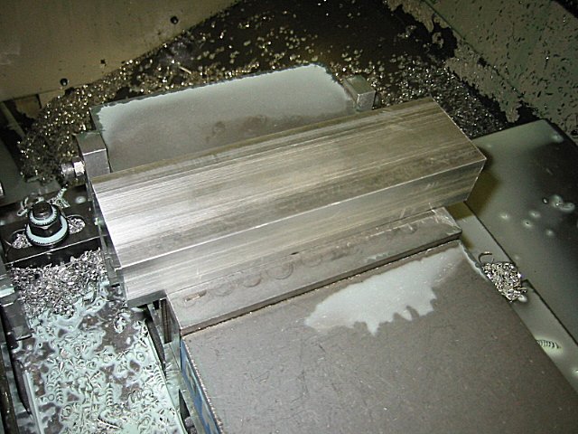
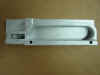
For the 1st operation, I of course started with just a block of aluminum...
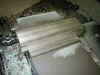
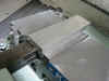
This pic is after the outside profile was roughed...
I used a 1/4" carbide ball nose endmill to machine the curved profiles. Here is a pic after the 1st operation was finished...
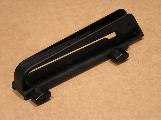
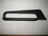
And here you can see what the de-handle looked like after it was bead blasted. Notice how much larger the finger gap is in this handle...
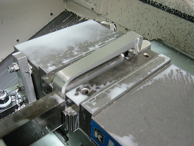
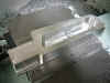
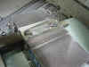
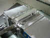
Here is what the setup for the 2nd operation looked like...
This pic is after I used a 3" shell mill to flycut the handle to about the right thickness. You can see the little angle block that I had to make to fit on the top surface of the handle, this was made so I could have a flat surface to clamp against in the vice. You can also see the little spacer block that I made for the inside of the handle, this block would keep the handle from squeezing together when the handle was clamped in the vice...
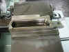
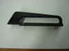
After the 2nd operation this is what the handle looked like. I removed the little spacer block to show what the inside of the handle looked like...
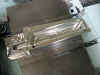
For the 3rd operation I machined the top side of the handle. Here is the setup that I used...
This is a bad picture, but maybe you can see the what machining was done. You can kinda make out the angle down inside the groove on top of the handle...
Here you can see what the de-handle looks like with the rear sight in place. Notice the step up from the top of the rear sight and the top of the handle. Most standard handles don't have this step up, but since I made the handle taller it had to have this step. But I don't think it's a big deal though, at least my fingers fit in the handle.
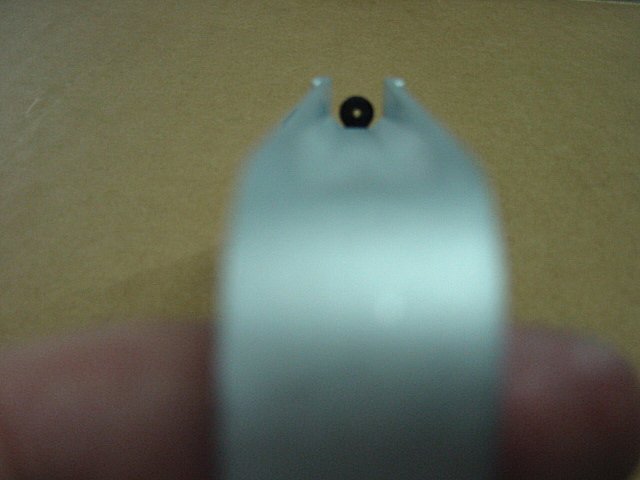
In this picture you can see how the rear sight looks compared to the top of the handle. The rear sight is in the lowest position and you still have a clear view through the channel of the de-handle...
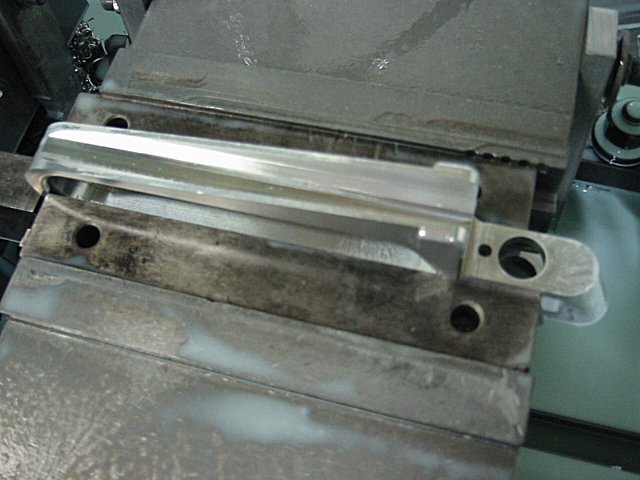
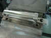
The last operation was the 4th operation. This operation will machine the bottom of the handle. Here is the setup...
This pic is after the 4th operation was finished. You can see the cuts with the special dove tail cutter that was made on both sides of the handle...
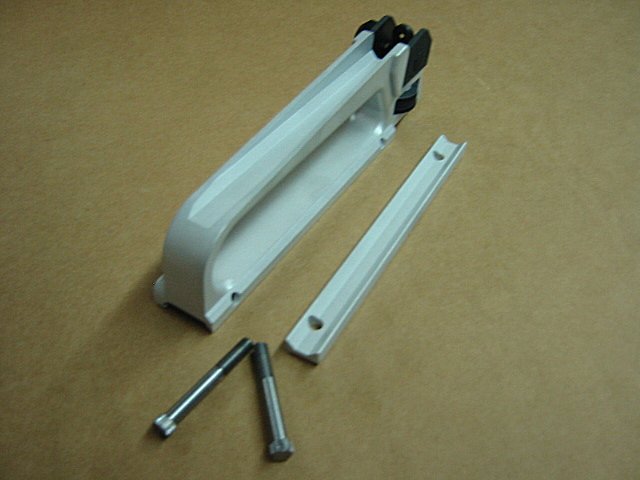
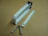
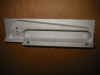
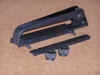
I didn't want to buy anything for the new de-handle besides the rear sight, so I also made the threaded studs, the knobs, the knob washers and the clamp bar. Here is a pic of all the parts I made (minus the knobs) for the de-handle, this pic has the rear sight that I bought...
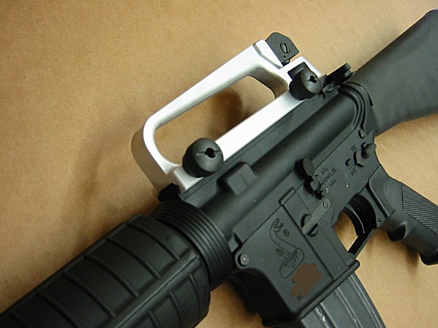
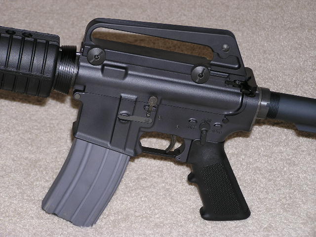
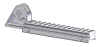
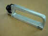
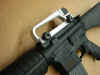
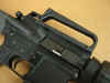
Here is what the new handle looks like installed. You can see that there is plenty of room to fit your fingers now...
This is a pic after I black anodized the aluminum parts and black oxide the threaded studs...
That is the end of the new de-handle that I designed and manufactured. After posting the progress pics on several different forums, I had a guy contact me saying he was interested in another new design for a handle. This guy has been in the military for a long time and he still uses the A1 type upper receiver. He said he hasn't converted to the M4 yet, because he loves his A1. He was wondering if it would be possible to make a de-handle that had the A1 look, so he could convert to the M4 and still have a taste of the A1. I started doing some thinking, and I decided it would be possible. So once again I started a new de-handle design. After many CAD hours, I finally had a design that I thought would work. I sent the file to the guy for his approval and he thought it would work. So I started the CAM and then the machining. As with the A2 and A3 upper receivers being very similar in machining, this A1 handle will be very similar to the de-handle that I machined. So I will cut out the machine work and just show you the good stuff.
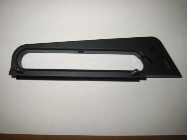
This is what the A1 de-handle looked like after the 1st operation...
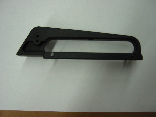
And here is what the finished product looked like after it was black anodized and the threaded studs pressed into position...
Here's the other side....
I was really happy with the way the new A1 de-handle and the A2 de-handle looked. Before I didn't much care for the A1 type rifles, but now I'm starting to like them more and more since I made this new A1 de-handle.
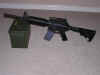
I
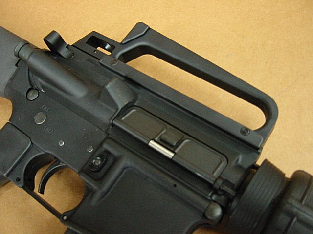
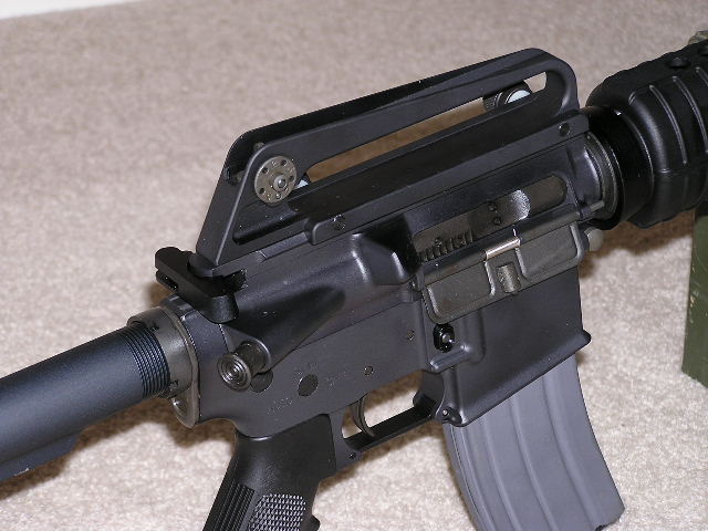
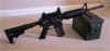
took some better pics of the A1 handle
to show you what it looks like installed
on an AR-15...
A
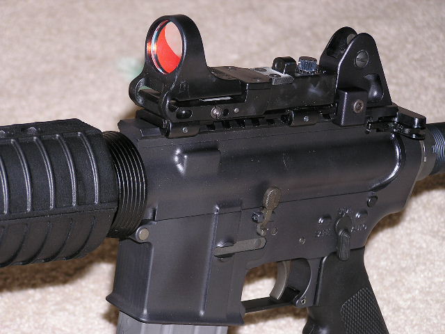
while back I bought a C-More
red dot sight. I really like this
sight and how it looks on my flat top
upper receiver. I only had one
problem, if the batteries ever went dead
in the sight, I didn't have a back up
sight system. I really like the A1
style of sight, since once you get it
set, you don't have to worry about
somebody playing with the knobs (like on
a A2 style sight) and getting the rifle
zero off. Don't get me wrong, I
like how you can adjust the A2 style
sight for windage and elevation, but
once I've set the rifle to zero, I
personally have never adjusted the
knobs. So with this in mind, I
wanted to make a backup sight for my
rifle with the A1 style of rear
sight. I sat down and started
doing some design work, and the first
design I came up with was a A1 rear
sight tactical rail (similar to the Mark
Brown Custom Flat-top Mount that
Bushmaster master sells). After I
had the design work finished, I started
machining the sight. After I had
the sight machined, I mounted it to my
flat top and then mounted the C-More
sight on top of the new rail. But
there was a problem, the C-More sight
was setting up too tall, and I couldn't
see the front sight post through the
rear sight since the C-more was in the
way. When I designed the rail, I
pushed the dimensions to the limits,
meaning that I made the rail as low
profile as possible. Before I ever
started the machining, I had a feeling
that I would have this problem, but
since I thought the new rail looked cool
I went ahead and machined it
anyways. Below you can see what
the rail looks like...
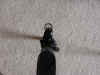
Since
I wanted a back up sight that would
work, I went back to the drawing board
and came up a new design. This
time I decided to leave out the rail all
together and just make the A1 rear
sight. With this design, it
wouldn't be as quick to remove the
C-More sight and the rear sight as one assembly,
since I wouldn't be able to just loosen
two knobs and pop the rail off, but I
don't install and remove this stuff that
often anyways so it won't make much
difference to me. I got the design
finished and started the
machining. I had a better feeling
about this sight and I was pretty
confident that it would work.
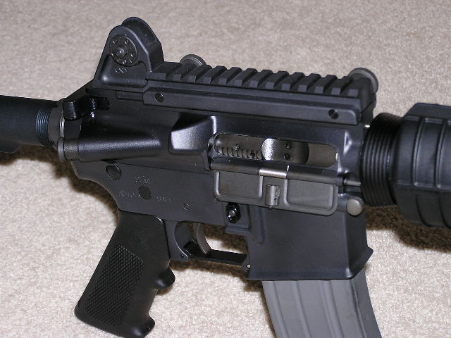
After it was machined, I mounted it to
the flat top upper and it was in the
perfect location. Below you can
see what the A1 rear sight looks like...
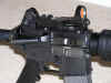
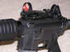
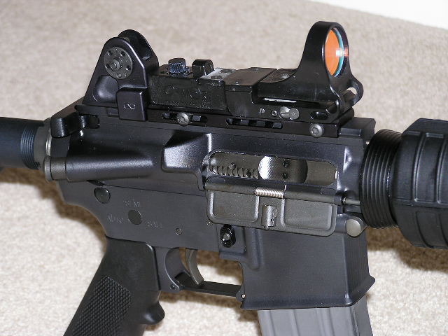
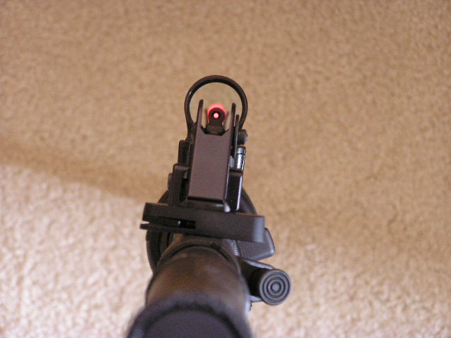
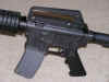
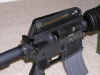
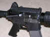
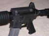
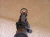
I
wanted to show you what the sights
looked liked installed as looking down
the rifle, so I tried to take a couple
pics from this angle. It was kinda
hard because the red dot showed up kinda
funny on the camera, but maybe you can
get an idea of how it looks from the
pics below...
I
am really happy with the way this backup
rear sight came out. Now I don't
have to worry about the batteries going
dead and not having a backup
system. I also like the A1 rail
sight too, even though it didn't really
come out as planned. If I have
enough people interested in the A1
detachable rear sight, I might consider
manufacturing a few of these.
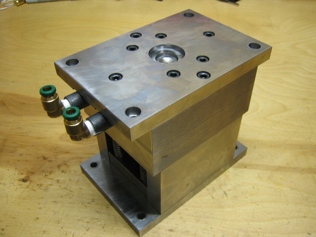
I've
been working on a mold for our injection
molding machines that will make plastic
knobs for the detachable carry
handles. This was the first mold I
ever tried to make. I learned a
whole lot during the process of building
the mold. Luckily, after I
finished the mold, it ran perfectly in
our machines. Below you can see
some pics of what it looks like. I
will do a more detailed write up on the
mold when I get some extra time. I
found out that there's a whole lot more
to building a mold than what I had
thought.

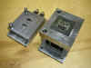
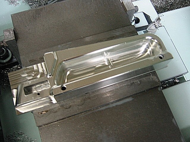
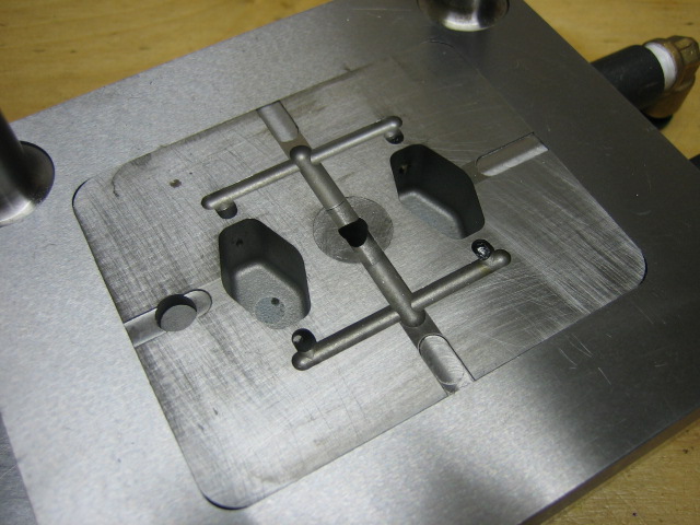
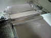
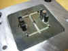
Core
side of the mold...
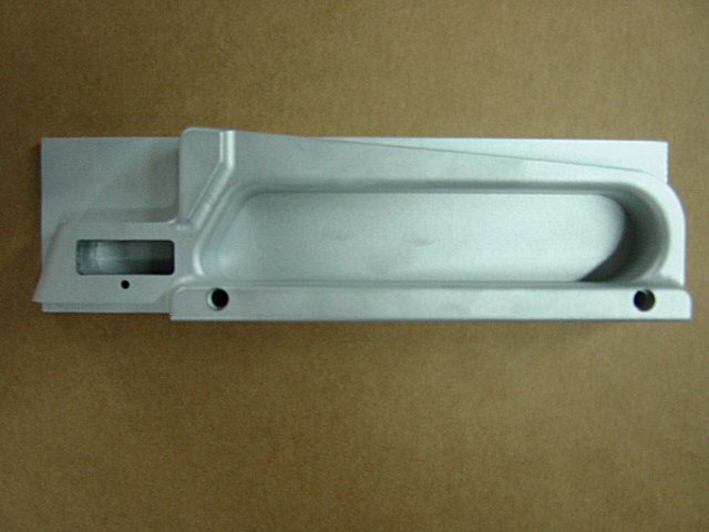
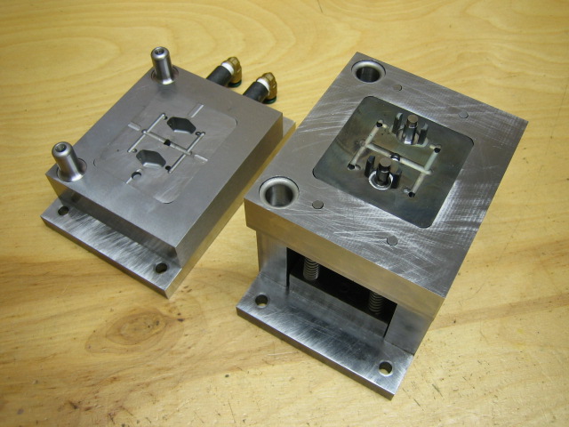
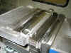
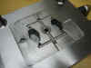
Cavity
side of the mold...
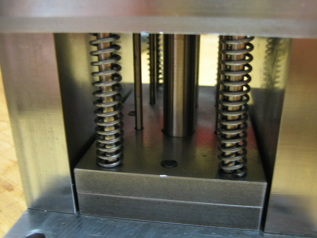
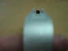
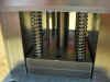
Detail
view of the springs and pins...
Buy
your A1 Detachable Carry Handle now
before they are all gone. Click on
the "Misc"
button at the top of this page, or click
this link.